Crossovers
The crossover is the heart of a loudspeaker, controlling how each drive unit behaves. Read on to find out how PMC optimises this vital part in order to give the most natural, accurate sound possible.
What is a passive crossover?
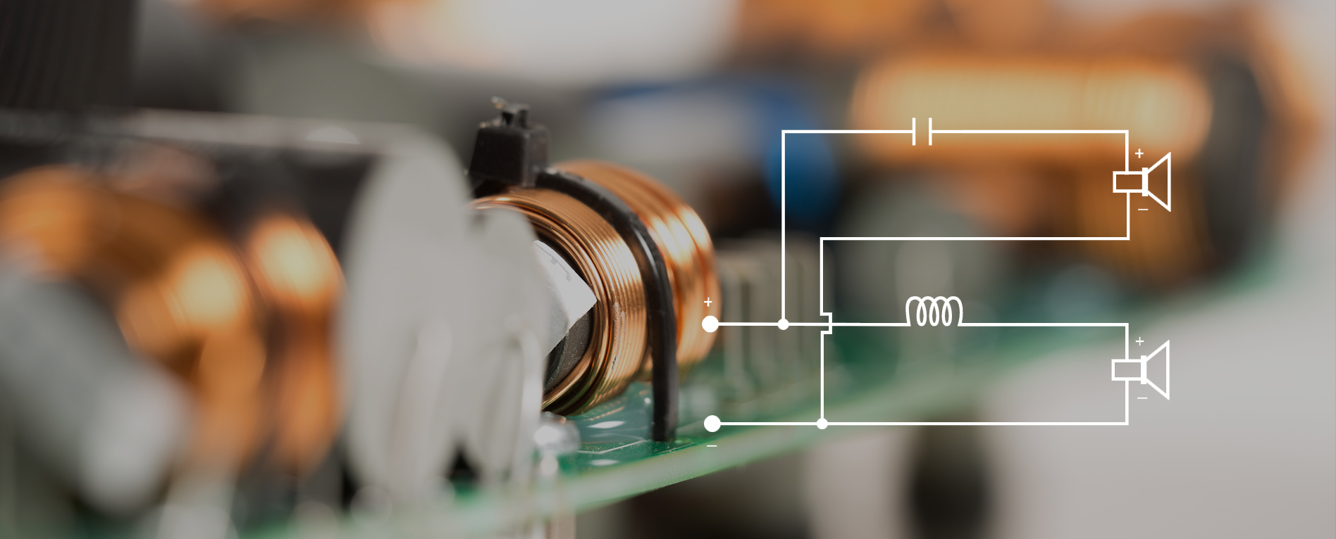
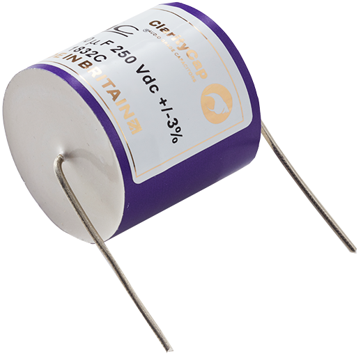
A passive crossover takes a high level audio signal from an amplifier (or from several amplifier channels if bi-amping), and uses passive components such as inductors, capacitors and resistors to filter this signal and deliver the appropriate frequency response and relative signal levels to each drive unit in the speaker.
The benefits of a passive crossover revolve around customisability – a passive crossover allows you to choose whatever amplifier you want to drive your speakers, and to have the ability to upgrade your front end components down the line if you wish.
Simulations vs reality
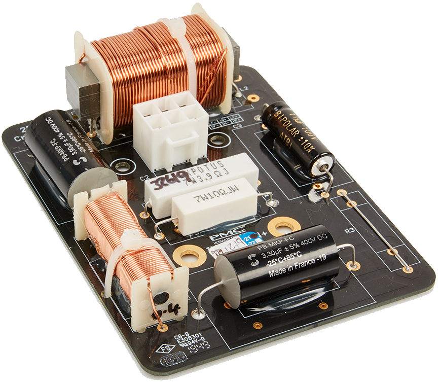
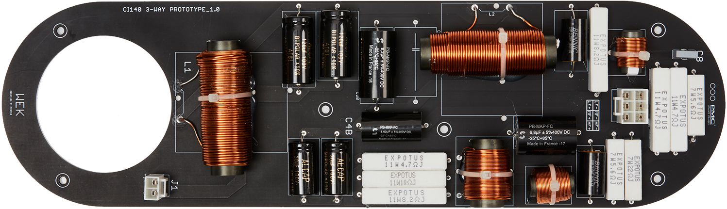
At PMC, passive crossover design begins with extensive simulations of various crossover topologies to give a good baseline setup which will measure well and give a smooth frequency response. Once this baseline crossover is built and verified to match the simulation, many companies may call the crossover finished and sign off on the design, but at PMC the hard work is just beginning! Extensive listening tests will now begin on the crossover, modifying one component at a time to slowly bring the voicing of the speaker towards the most natural, transparent and accurate sound possible, with each iteration also undergoing a full suite of measurements to corroborate what is being heard with what can be measured.
Trying a thousand components - the journey to finding the best
Once a final set of component values has been decided on, different brands and styles of each component value will be swapped in and listened to in order to find the best sounding version of each component. To give an example of how exhaustive this process can be, take the example of a single inductor – variants to try can include air core, iron core, steel laminate core, different wire gauges, different wire materials or profiles etc. Multiply these variations by the total number of components on the board and it is easy to see how long the process can take.
The Final Tweaks
Finally, the layout and positioning of the components on the PCB is optimised to remove any unwanted interactions between different passive components – inductors must be spaced as far away from each other as possible, and in opposing orientations to prevent any magnetic coupling and ringing that could otherwise occur. Only when all of these steps have been perfected will we sign off on a crossover design.
There are certainly easier and faster ways to design a functioning crossover, but at PMC we know that the extra effort we put in is worth it to give the customer a truly excellent audio experience.
What is an active crossover?
The majority of PMC active crossover designs utilise Digital Signal Processing (DSP) to further their functionality. A PMC DSP crossover takes a low-level signal from either an analogue or digital sound source, separates the audio signal into the correct frequency bandwidth and relative level for each drive unit, uses EQ to further linearise each drive unit’s response, and digital delays to correct for time alignment and phase differences between the drive units.
Each filtered signal is then fed to a separate amplifier channel for each drive unit, meaning that there are no passive components placed between the amplifier and drive unit. This gives the amplifiers much greater control over the motion of each driver’s diaphragm, allowing for even more accurate sound reproduction.
Why use an active crossover?
There are numerous benefits to using digital active crossovers; they give the designer complete control over the behaviour of the drive units in both the frequency and time domain, allowing for a much more accurate speaker design to be realised. A digital crossover setup will also often allow for the inclusion of user assignable EQ and other filters to allow for seamless integration into any room or system. Overall sound system complexity may also be reduced for the end user, as theoretically only a music source and the speakers are required, dispensing with the need to purchase a separate pre/power amplifer, DAC, etc. as all of these are now built into the speakers themselves.
These components are now all specified by the speaker designer, allowing them to select the best possible ADC/DAC chips, DSP platform, and amplifiers to work with the intended drive units, ensuring that the best possible performance is extracted from each component. By having control over all of these components, it is also possible for the designer to implement highly accurate limiters and protection systems so that the customer can run their speakers at any playback level with the confidence to know that they are not at risk of damaging any of their components.
How do you specify a crossover?
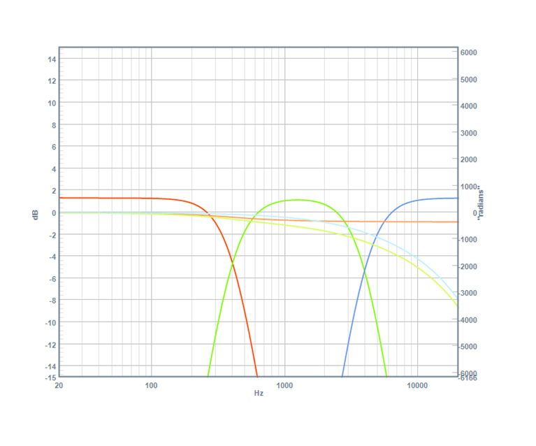
A crossover filter is defined by several parameters: The knee frequency (the frequency above/below which it begins to reject an incoming audio signal), the crossover slope (the rate at which it attenuates the incoming audio signal beyond its knee frequency), and the Q, or Quality of the filter, which defines subtle changes to how the filter behaves around the knee frequency and in the transition between the filter’s passband and stopband.
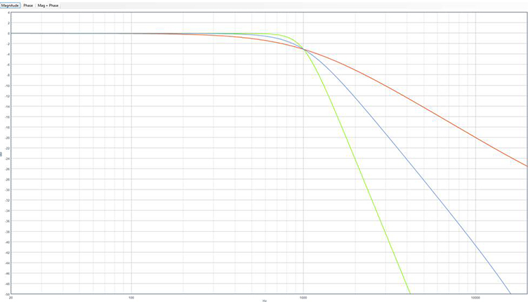
What is the most basic crossover?
A filter’s slope is specified in dB/octave, and defines how many dB the filter attenuates a signal by for each successive octave beyond the knee frequency.
In a passive crossover, a steeper crossover slope requires a more complicated circuit design with more components, and in turn is harder to design and optimise. The most simple crossover filter has a slope of 6dB/octave, and is known as a first order crossover. This can be realised with a single capacitor for a high pass filter, or a single inductor for a low pass filter, and many companies suggest that this is an optimal solution for a crossover, citing simplicity and purity as reasons.
Why simplicity can be costly
Unfortunately, because of the extremely slow attenuation rate of a first order crossover, a drive unit filtered with one will still be outputting a very significant amount of energy several octaves beyond its intended crossover frequency, leading to potentially severe amounts of distortion as either a tweeter is overdriven at lower frequencies than it is capable of producing, or a woofer/midrange is driven up the region where it suffers from cone breakup. A first order crossover can also lead to serious anomalies in the off-axis performance of a speaker, as the woofer’s directivity will get increasingly narrow above its intended crossover frequency, leading to undesirable lobing and comb filtering when overlaid with the much wider dispersion of the tweeter at these high frequencies.
24dB Crossovers
To avoid all of these issues and give an accurate, linear sound reproduction, PMC makes use of complex 24dB/octave, 4th order crossover filters. These filters ensure that each drive unit is only operating in its most linear and accurate region, and that the dispersion characteristics of each drive unit can be matched around the crossover region. This ensures that PMC speakers give clean, low distortion sound with high power handling, and an incredibly wide, even dispersion.